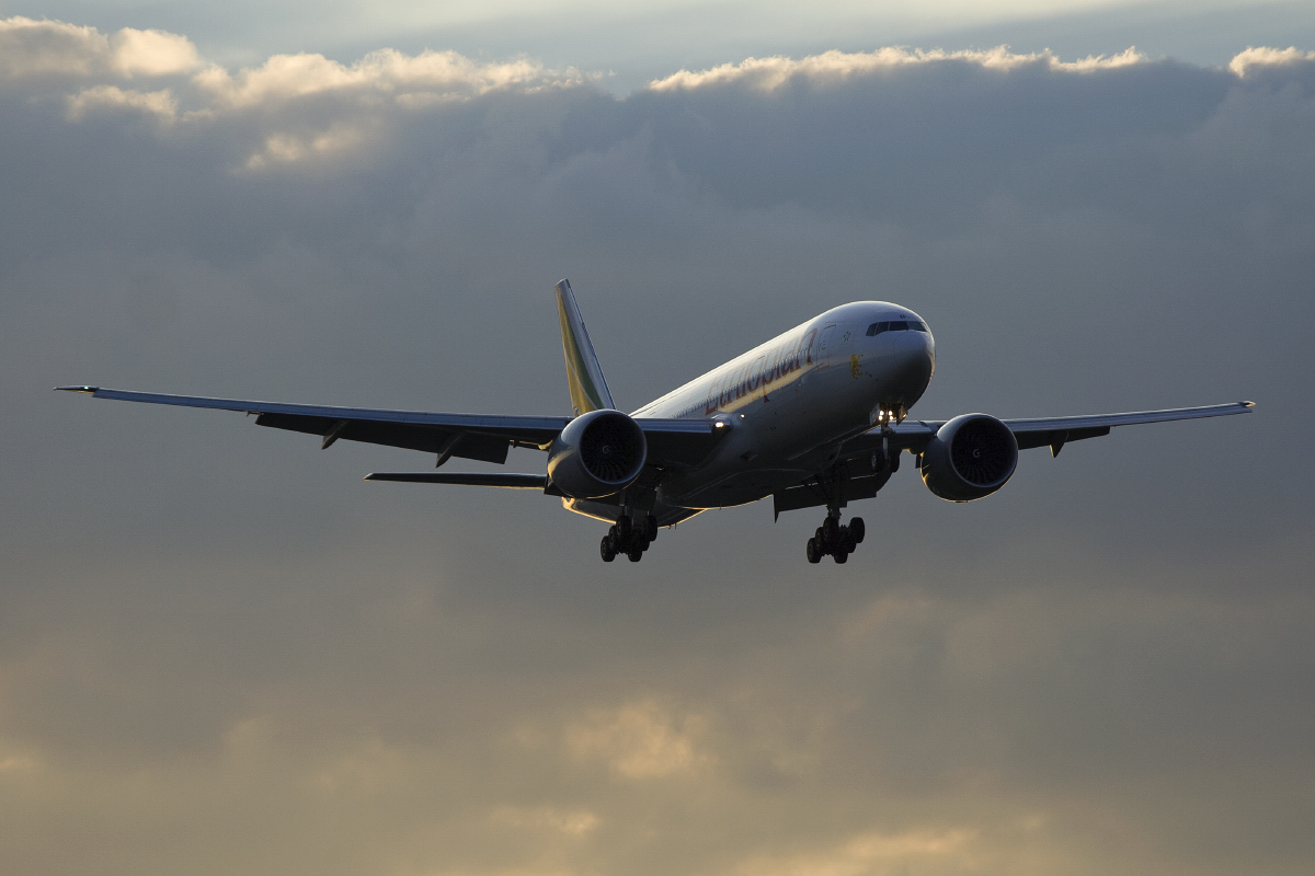
A quote has always struck with me regarding airplanes. It’s from Bill Lear who said “If it looks good, it will fly good”. I have never been a big fan of Learjets, but it sure sounds true. It seems that the best-selling planes do share a characteristic : they look majestic, balanced, sleek and seem to have natural proportions. They don’t look like the pile of refined metals and plastics that they really are. They make us feel comfortable to step inside and take off to the sky.
We owe this to the engineers and designers. One thing i have yet to understand, is how much does the actual aerodynamics and engineering have to do with the look. Does someone with engineering knowledge “draw” a plane or does it emerge from the combination of the various engineering departments drawings? It has to be both necessarily, but I wonder how much freedom there is in shaping an aircraft…
The landing gear
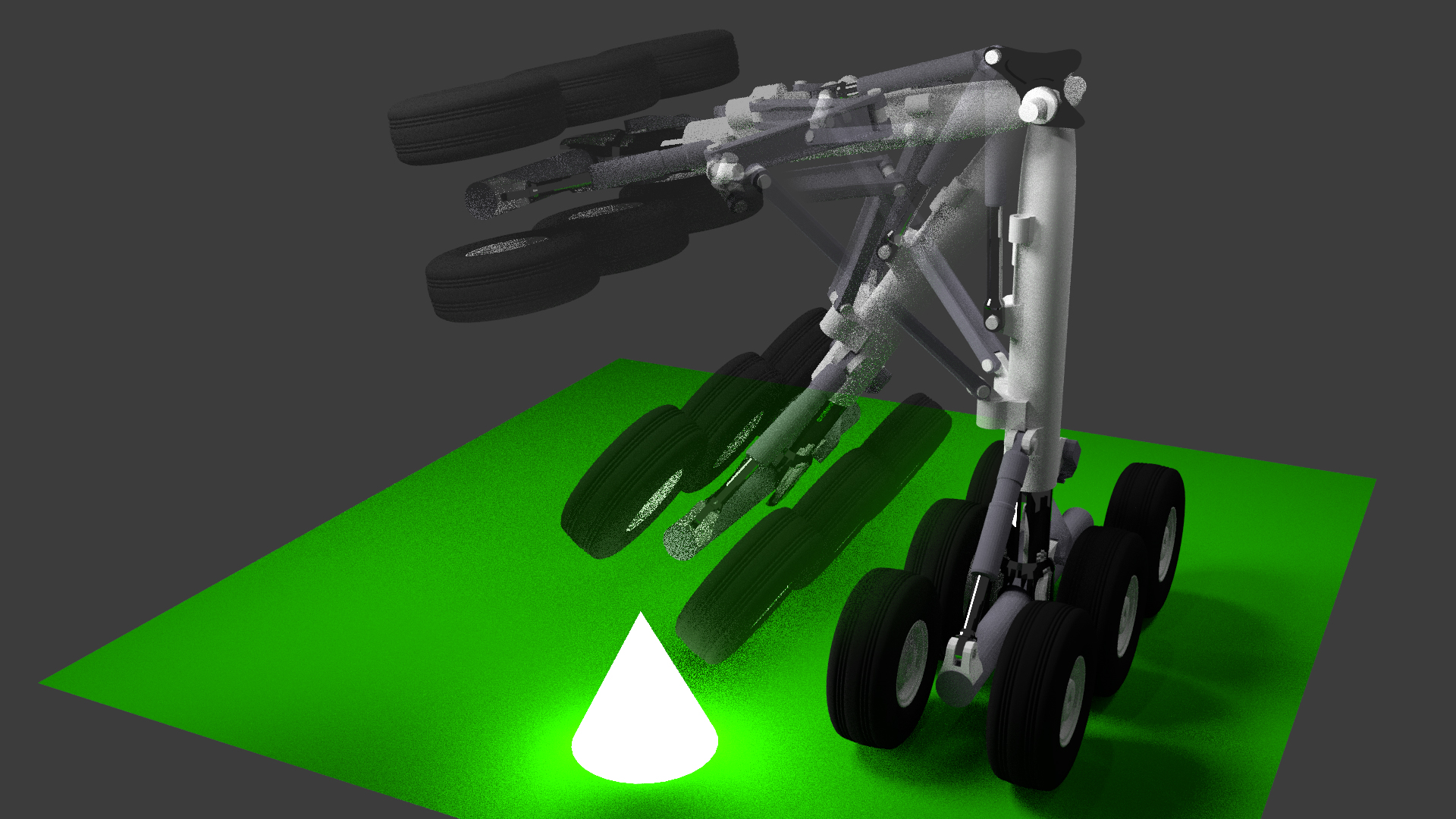
What I want to talk about today is a little project i took on this year in Blender. I have always been fascinated with landing gear mechanisms. When deployed, they look very complex and yet, once the aircraft leaves the ground, they fold almost as if by magic into the fuselage leaving nothing more than invisible seams in the fuselage.
A few other things are curious about landing gears. One main gear can absorb the energy of the whole airplane on a rough landing. The wheels don’t spin before the aircraft touches the ground. A touchdown can often result in intense excentric rotation of the wheels that the tire and gear has to absorb.
Now that we have dreamed a little, let’s dive into to project itself.
Finding drawings
It’s easy to talk about it now but it took me quite a few days to understand the movements and parts that together form a landing gear.
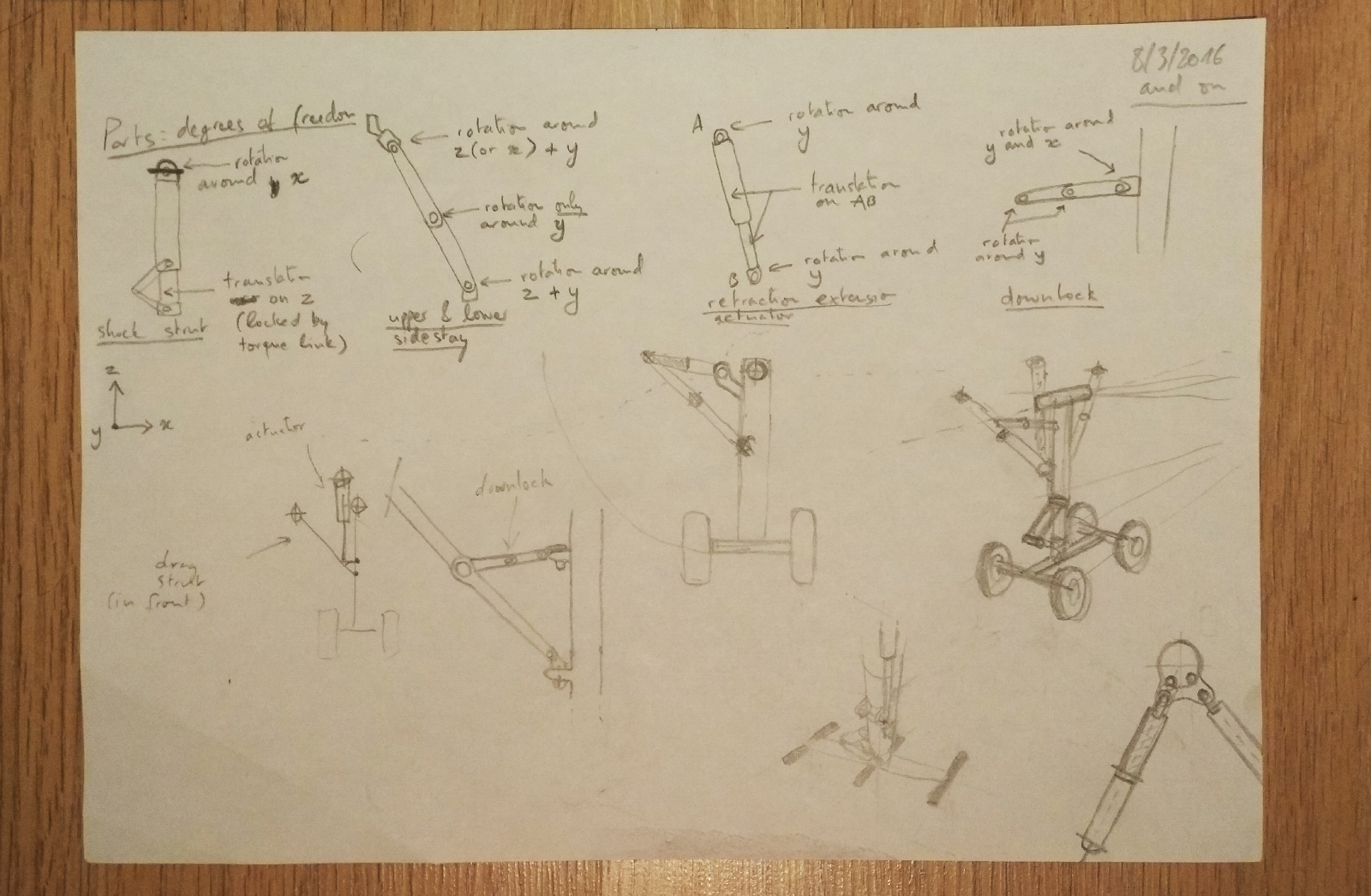
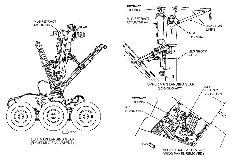
It seemed like a good challenge to try to model one, and animate it. Thus began the process of rounding up some technical drawings and understanding the basics of the retraction mechanisms. I first challenged myself to guess how it might work and started a few sketches on a piece of paper. As I was getting more understanding and finding a few diagrams online, I kept adding drawings and eventually put the sheet over my dining table, where it ended up staying for a few months.
There are almost as many designs as there are airplanes, but I wanted to focus on a main landing gear retract of a heavy airliner. I first wanted to do the 787, as I like its clean and compact design. I ended up choosing the B777 gear because it turned out it had the most drawings. My main objective was not to model the parts too precisely, but model the interaction between the main parts and animate the movement.
Breaking it down to the main components
To make it simple, there are 5 main components in the gear itself and the retraction mechanism.
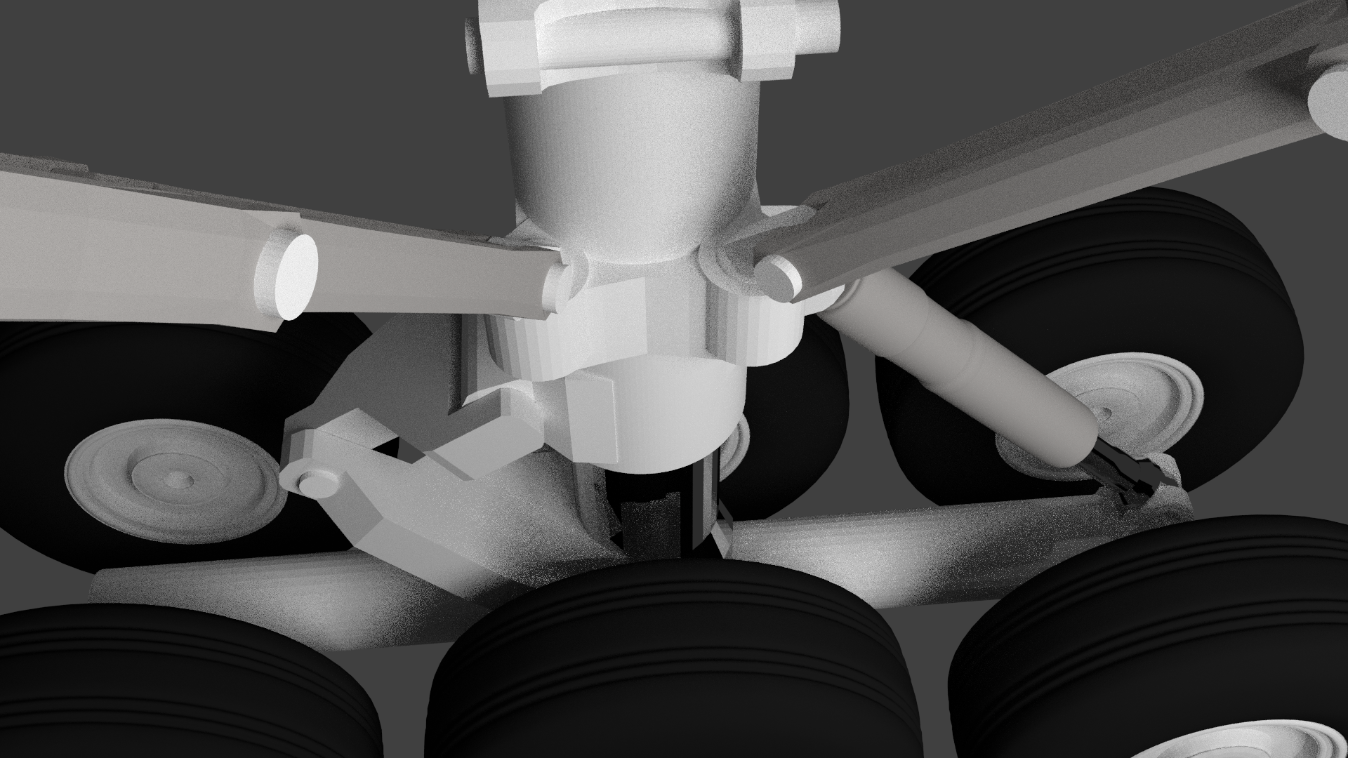
The main part that connects the body of the aircraft to the bogie is called the shock strut. This component most of the weight of the aircraft. It also houses the shock absorber that helps dissipating part of the energy during touchdown.
Next there is the drag strut and the sidestay. These parts have one main purpose: add rigidity to the whole landing gear and help locking the gear in the down position (I am not a 100% sure about the names of these two parts, please correct me if I’m wrong).
In order to lock the landing gear in the down position, there are two downlocks.
Last but not least, the retraction and extension actuator. This part’s job is to rotate the 3 ton Boeing 777 landing gear into the body of the aircraft, using hydraulic power.
The kinematics
One of the challenging parts of this project was understanding the various degrees of freedom (DoF) of different parts. It determines how those parts can move in relation to other parts.
For example, the DoF of the main column (shock strut) is pretty simple, I’m sure you can easily guess it.
The torque link and shock strut movement is very straight forward too, as all the parts only have one or two degrees of freedom. Rotation around one axis and/or translation on one axis.
The difficulty lies within the drag strut, side stays and downlocks. Without exact documentation, it was impossible for me to determine dimensions and trajectories of these parts.
This is where the guess-work began. It was easy to observe from various gear swing videos that the lower and upper sidestay “folded” upwards, as well as the downlock.
What I couldn’t figure out, and actually never resolved, is the aircraft body – upper sidestay connection point. Kudos to Luca Iaconi Stewart for making it work on his paper model.
Actual modeling
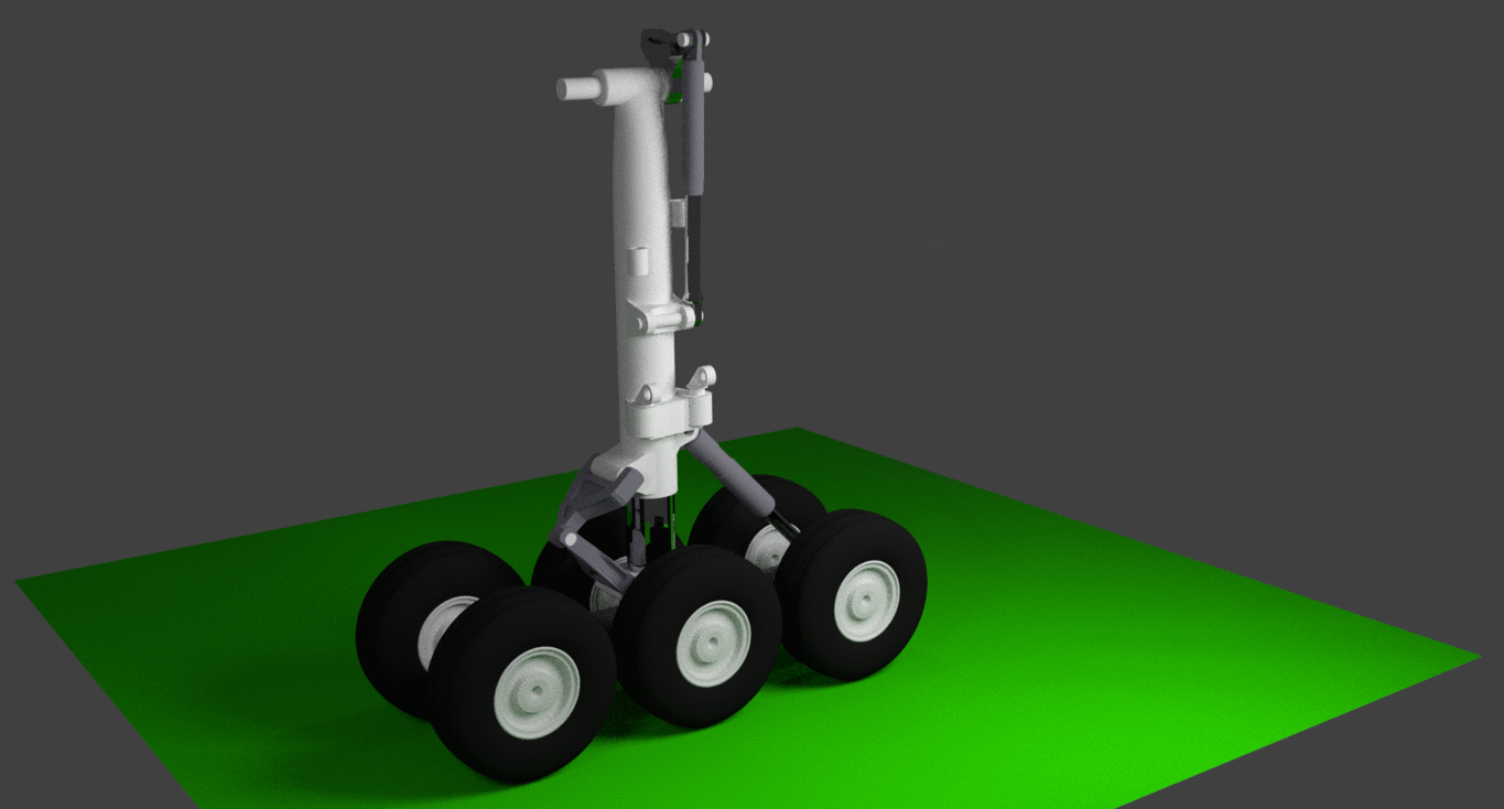
Drawing up the components was the fun part, although some parts were a bit more challenging than others, like the torque links, especially since they were modeled to interact with one another. I wasn’t interrested in modeling the landing gear in great detail, so it didn’t take too long before I had all the parts ready to go.
This job took roughly 10-15h to complete, given that I was learning some techniques on the fly.
Constraints
After all the parts were ready, it was time to create some constraints. In other words, determine how each part is allowed to move.
This means two things. First, how each part is connected to other parts. Second, what are its degrees of liberty. There are 2 types of DoFs, rotation and translation.
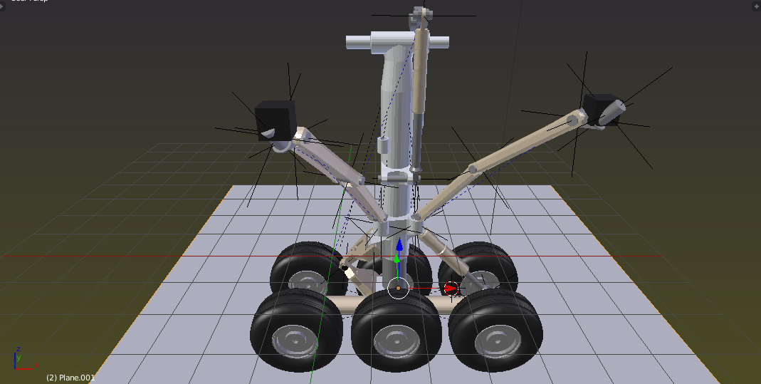
In blender, assigning DoFs can be achieved using empties for example. These are virtual 3D axis objects to which you can tie other objects and add constraints.
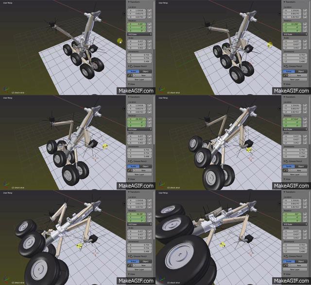
In the image above, each black cross represents an empty.
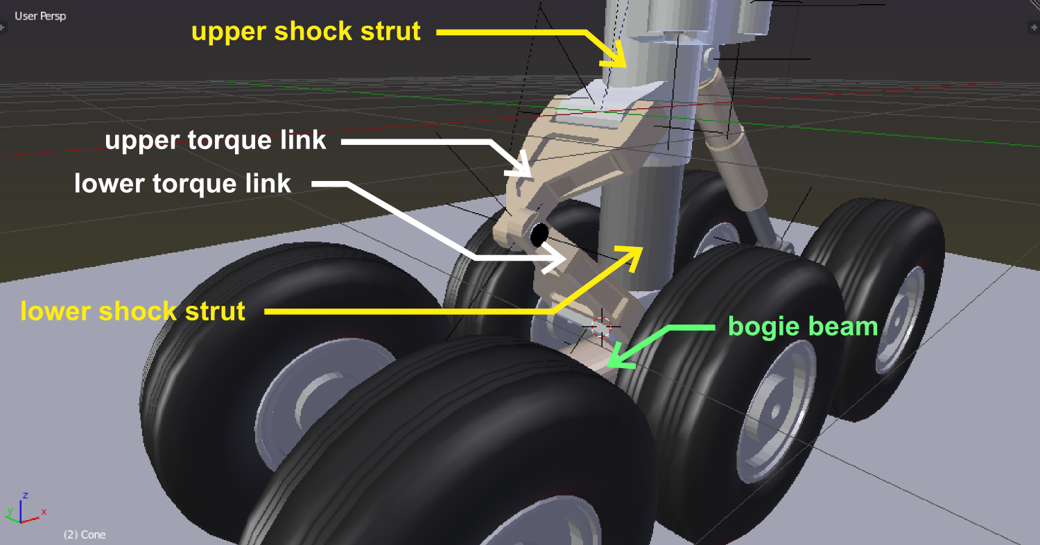
For example, let’s say I want to set the constraints to the shock strut. First I need to determine the different dependencies. If I don’t consider the side-stays for a moment, I can see there’s 5 components that are all moving in relation to each other. Upper and lower shock strut, upper and lower torque link and bogie beam. I need to determine the parent-child relationship between the components first. There are two groups. Since the main gear always needs to go straight, it needs a torque linkt. The upper torque link is the upper shock strut’s child, and the lower torque link is the lower shock strut’s child. Joining these two parts keeps the bogie straight. The bogie itself and all of its components is also a child to the lower shock strut.
As a result, whenever the upper shock strut moves, the rest of the parts moves along with it.
The unresolved problem
See the two black cubes? It is where the drag strut and sidestay are connected to the aircraft. I couldn’t figure out the axis around which the grey part is supposed to rotate around.
I have still an unresolved problem with the connection between the lower and upper sidestays, so I haven’t incorporate the downlock arms yet.
For now, the objectives haven’t been attained fully. Stay tuned for part two…
